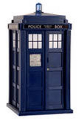
Dr. Who's TARDIS
Bill's TARDIS I
TARDIS stands for "Time And Relative Dimension In Space," from the BBC TV series, "Dr. Who." Local amateur astronomers gave this name to Volna's first heated observatory.
TARDIS I, finished in 1989, has provided an enriching experience for hundreds of school children and adults in several American cities.
On loan to the National Science Foundation, it served scientists at the Amundsen/ Scott South pole station for two years without failure at -100 F.
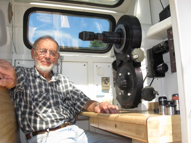
Bill inside TARDIS I.

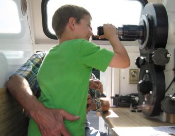
Bill with two budding astrophysicists.
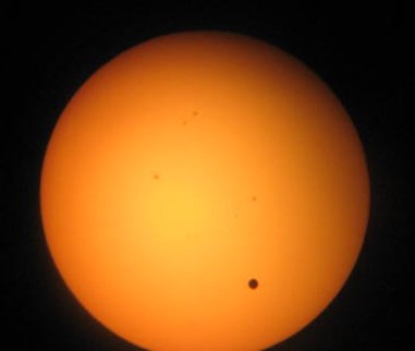
Venus transit
TARDIS II
The objective in building TARDIS II, a design proven with TARDIS I, is to create a telescope which will provide a safe, comfortable viewing experience for people who are physically challenged.
Before TARDIS II, a person in a wheel chair could not possibly enjoy the raw beauty of the planet Saturn, Jupiter, or the craters on the Moon, other than artificially by digital electronic devices. Also, many viewers consider it a challenge to climb a ladder to an eyepiece presented at an awkward viewing angle.
TARDIS II includes computer control and a larger heated viewing room that meets federal requirements for wheel chair accessibility. It brings the universe into a comfortable room, free of mosquitoes in the summer or the need for warm clothes in the winter. The seated viewer looks horizontally straight ahead to view objects anywhere in the sky from the horizon to the zenith. After a long night of star gazing, point the telescope down, lower the thermostat, lock the door, and retire.
As in TARDIS I, this observatory necessarily employs a refracting type of telescope design long known for superior image resolution while viewing extended surface objects such as the Moon, planets, and Sun. Refractor type telescopes are unsurpassed for separation of close double stars. The design will accommodate a wide range of lens types, focal lengths, and optical apertures up to, and including, 10 in. (25 cm.).
In response to considerable interest in TARDIS II, the following pages will show the progress of construction as it occurs, with pictures and captions that some viewers may find interesting, while others may gain knowledge and understanding useful for their own telescope designs.
Over the 30 years since TARDIS I was started, many new and exciting design tools have become available. Among these, ViaCAD 2d/3d, a drafting software program, was purchased at Office Max for $99 and became the genesis for design of TARDIS II. Without this software, the project would not have begun.
Most of the primary parts of the telescope and azimuth/altitude mounting for TARDIS II will take form first as a 3D solid drawing, then as a wood pattern, and finally as an aluminum casting that requires minimum final machining.
The first casting, called the "tee casting," now finished, required a full-sized wood pattern and core box made of hundreds of small pieces of pine held together with Elmer's Probond or Tite Bond II glue. Alternate "pie-shaped" pieces, with reversed adjacent grain patterns and staggered joints between layers, has proved to be a very cost effective way to get large pieces of stable wood for a pattern. After three years the pattern has shown no detectable change in dimension (>.010 in.).